Building the SFI/Turbo V-6 Vega
by
Dave English
Many of my H-Body friends have asked me to document my follow-on project to my previous LT1 Vega conversion. This is the story of my latest effort; swapping a fuel-injected, turbocharged 3.8 Liter Buick V-6 into a 1977 Vega Hatchback.
The idea for this project grew out of the generosity of
“Vega Man Larry” Heagren. When I sold my LT1 wagon, Larry
encouraged me to pick up another project. I had already been tinkering
with a ’77 Vega Hatchback that I planned to purchase from Sherman Wright,
and Larry had a complete ’81 carbureted Turbo set-up that he had
previously run on another Vega. When I sold the LT1 car to
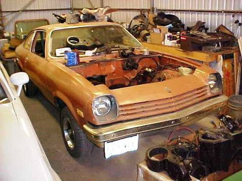
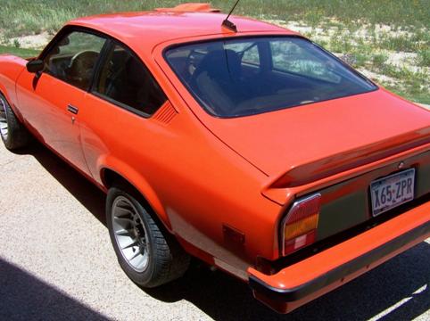
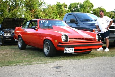
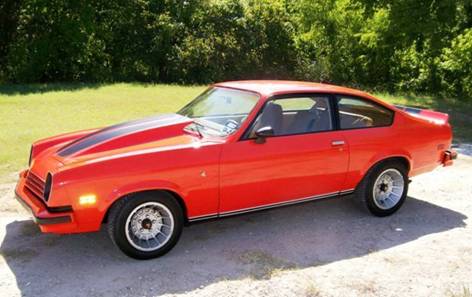
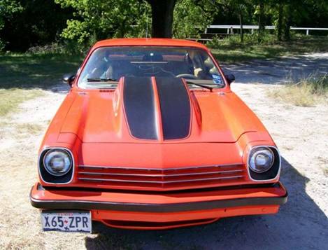
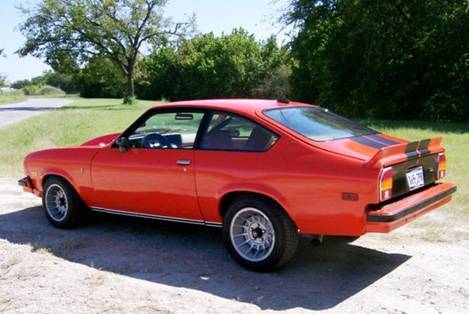
The Rolling Shell!
'77 Vega with NA V-6
NA V-6

Stock
Living in
I found another early Buick engine and set it aside as the
basis for the Turbo motor. I planned on using the stronger turbo
crankshaft with rolled and filleted main and rod journals, and a set of
.030-over forged aluminum pistons. I found most of what I needed by
watching eBay and the Turbo Buick “Parts for
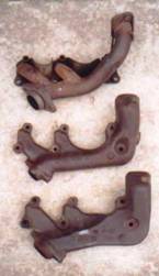
In the meantime, I learned a lot about Turbo Buicks. The ’81 set-up was the least desirable among the early carb/turbo designs because it used a normally-open wastegate instead of the normally-closed design. I would either need an M4ME electronic feedback Turbo carb, or I would have to find a way to make a manual carb power valve go full rich under approximately 4 p.s.i. of boost. The ’81 and ’82 exhaust manifolds were more restrictive than the other years.

Although I enjoyed the technical challenges this presented;
obviously, this was not going to be a high-performance screamer. The
Buick carb/turbo design did not lend itself to a good, uniform flow to the
outboard cylinders. The boosted fuel/air mixture just dumped into a
center port from which all the intake runners were fed. Although I found
a great NOS non-electronic Q-jet carb and devised a way to make the power valve
go rich under boost using a
'81 Carb/Turbo Buick Manifold Set-up
Electronic Power Valve Control
And then it showed up on eBay—not complete, but the basic foundation was there. A rebuildable turbo, throttle body, intake manifold, fuel rails, and injectors from an ’85 Grand National. I told my wife she was getting it for me for Christmas, and I felt like I stole it when I won the auction for $130, plus shipping!
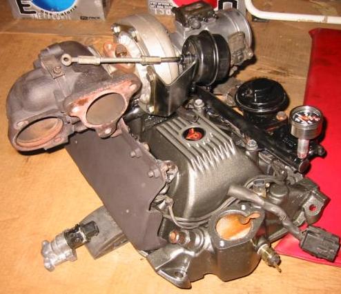
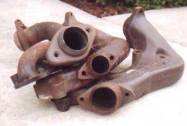
'85 Turbo Manifold (example)
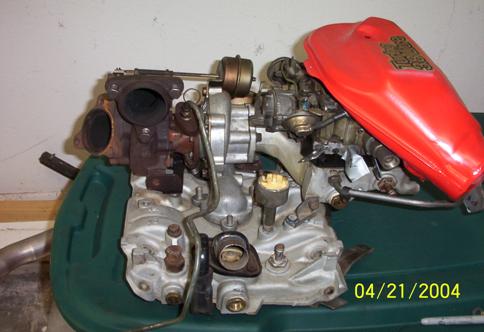
'85 Turbo Buick SFI Engine (example)
When Mark got ready to start on my engine, we hit the first snag. I had a set of .030 forged TRW pistons I purchased for the engine that was sold. The engine with the rod knock we pulled from the Vega had been previously rebuilt and bored .040-over! Since forged Buick pistons aren’t available in .040-over, the best option was to find another stock block. Other than the Stage I and II blocks, the strongest blocks in the Turbo Buick cars were the -109 blocks that were used from mid-1985 through the end of the production run (also used in the ’89 Turbo Trans Am). It is increasingly difficult to find a good Turbo -109 block that hasn’t been thrashed, overbored, rebuilt, or abused. When you can find them, they command a premium price. Fortunately, the naturally-aspirated Buick V-6 1986 and 1987 GM RWD cars all used the same -109 block with one minor difference—the turbo oil drain hole on the front of the block was cast solid. Other than that, the block and heads are identical. I went to my local wrecking yard, and located six potential donor cars with -109 blocks, and settled on a 1987 Grand Prix as the best candidate. I gave the owner $150.00, and he delivered it to my home. Twenty-four hours later, I had the block completely disassembled and took it to Samford Racing Heads as the bare canvas for my new Turbo engine.
The engine is built around a standard “-109” Block from a non-Turbo 1987 Grand Prix. The pistons are TRW Forged .030-over. Connecting rods are standard Turbo Buick -763 castings with ARP bolts. It is balanced at 38%. The Main Bearing caps are held in place by ARP studs. A double-roller timing chain replaces the stock unit. Heads feature a 3-angle valve job by Mark Samford; Manley "severe duty" 1.71" intake and 1.5" exhaust valves are used with LT1 springs at 105 lbs. seat pressure. ARP head studs are used to fit the heads to the block. The Reed cam uses profiles from Sod-Buster 4H260 intake (210@.050”) with a Torque-Master TM252 exhaust (205@.050”).
The engine uses a drivers-side polyurethane mount from RJC Racing to control torque, and a standard rubber on the passenger’s side to dampen vibration. The transmission mount is a standard Energy Suspension TH-350 polyurethane mount from Auto Zone.
'85 Intake and Exhaust on Bare Block
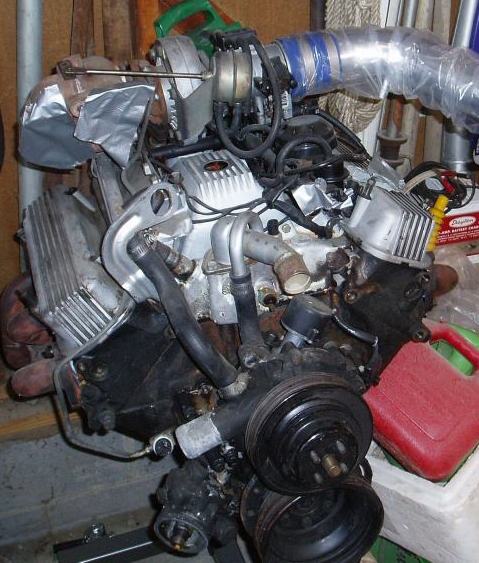
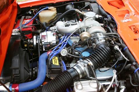
'85 Turbo Intake and Exhaust Plumbing
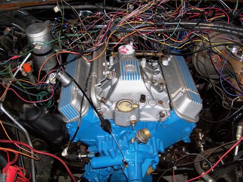
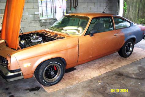
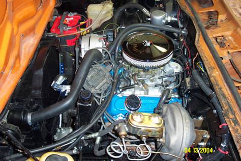
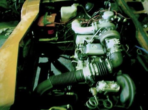
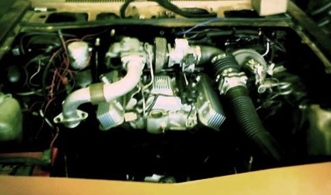
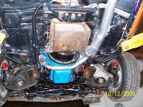
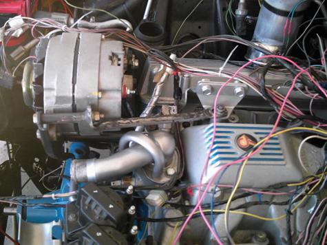
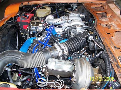
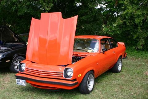
Engine installed !
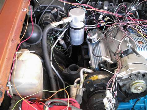
Having put the fuel injected LT1 in my previous Vega, I felt comfortable with fuel injection, sensors, wiring, and computers. The ’84-’87 SFI/Turbo was an early second-generation design, but it basically used similar sensors and design logic as the LT1 and even the current LS-series engines. I spent countless hours on the Turbo Buick message board sites, and found one fantastic source— www.gnttype.org has more good information in one location than any site on the web. One of the first things I learned was that since the earlier ’84-’85 computers were more rare and expensive to replace you could set up the earlier ’84-’85 engine with the ’86-’87 computer. Even more interesting was the fact that the same basic computer was used with a different replaceable chip in many of the FWD 3.2 and 3.8 liter V-6 cars built by GM between 1986-1989. If the computer was the same, the engine control wiring harness would also have to be very similar to the SFI/Turbo harness. One improvement over the ’84-’85 ECM and harness is that the ’86-’87 set-up added a manifold air temperature sensor for improved throttle response and lower emissions. Since I didn’t have a Turbo donor car, and I didn’t want to pay $600.00 for a custom harness, I decided to pull a computer and harness from a 1987 Olds ’98 Supreme and start modifying. I compared the wiring diagrams for an ’86 Buick Century FWD car to the ’86-’87 Turbo Regal and found it only required changing about five wires to make it work. You can find the wiring diagram for the Turbo Buck here: http://www.gnttype.org/techarea/ecmsensors/regal_ecm.jpg. I added a connector and wiring for the Turbo Wastegate Control Solenoid and spliced the Third gear and Fourth Gear (2004R) input wires together take an input from a third gear pressure switch from the TH350C transmission I am using. This not only allows torque converter lock-up, but also provides timing and boost adjustments to the ECM. The ’84-’85 Turbo Buicks used a mechanical fan and standard v-belt accessory set-up. I hoped to retain that, but I would have to go with a small 14” diameter fan to avoid hitting the steering box. Since the ’86-’87 ECM was capable of controlling the fan based on coolant temperature, I decided to use a 16” Zirgo 2950 CFM puller fan built into a Monza Towne Coupe fan shroud. All the ECM wiring is on a dedicated fuse and relay Circuit Boss from Painless Wiring. Power for the engine control harness comes straight off a 12-gauge hot lead from the battery to a relay that is activated by the existing Vega 12-gauge pink "Ignition Hot" lead. Three fused feed lines tie into the ECM and sensor wiring from the relay. That way, additional loads are not placed on the Vega wiring. Follow this link for more details on converting a FWD GM V6 engine harness to work with the ’86-’87 Turbo Buick ECM: http://dave.h-body.org/Converting%20a%20GM%20FWD%20Wiring%20Harness.htm . I decided to use a used stock prom for starters, and I bought a CALPACK chip from www.GMPartsDirect.com. Another popular electronic upgrade is to swap to the later 3-coil pack used in late ‘80’s through mid-‘90’s GM FWD cars. This is a simple upgrade; read about it here: http://www.gnttype.org/techarea/ignition/type2coils.html . One thing to remember is that whichever ignition module you use; you MUST ensure the module housing is grounded to the engine block, either through the mounting bracket or a separate ground wire. I had lots of intermittent ignition problems (described later) that I thought were related to bad ignition modules that were caused by the fact that the bracket was powdercoated and the module was not getting a good ground through the coating. Once that problem was solved, I was good to go with my wiring and electronics.
The older GM ECM cannot be exposed to temperature and weather extremes like the newer ones used in the LT1 and later vehicles. This required me to locate the computer inside the car. I found an old Turbo Regal RH kick panel that had provisions for mounting the ECM and modified it to mount behind the console. I used a Dremel tool to cut a hole in the firewall and a rectangular computer desk grommet to pass the wiring through and close the hole.
One of the weaknesses in the earlier SFI set-up was the Mass Airflow (MAF) Sensor. They had a tendency to fail, and were expensive to replace. Fortunately, the later LS1 MAF is more reliable; flows more air, and can be used with a device called a MAF Translator to work with the Turbo Buick ECM. I decided to go with the MAF Translator Plus, which also allows some custom tuneability for spark and fuel delivery by modifying the MAF signal to the ECM. Read about how it works and how to install the MAF Translator by clicking here: http://www.fullthrottletech.com/ and navigating to the install instructions page
Exhaust
As mentioned earlier, many of the exhaust parts from the
’79-’83 carb/turbo Regals will interchange with the
’84-’85. I experimented with the stock tubular headers that
were used in ’83-’85, and concluded that they did not provide enough
clearance. I found a 1980 Turbo Monte Carlo at my local wrecking yard and
tried cast manifolds from that car but the crossunder pipe flange on the
passenger side hit the RH fender well. Finally, I decided to use
the smaller ’81-’82 cast exhaust manifolds from the carb/turbo
stuff Larry Heagren gave me, and the larger ’80 Turbo Monte Carlo
up-pipe. I had an oxygen sensor bung welded into the up-pipe for the
ECM. The manifolds were coated with a black heat-resistant powder coat, and
I painted the up-pipe with Eastwood Silver 1200 degree manifold paint.
Despite the tight clearances, Terry St. Pierre at The Muffler Shoppe in
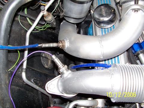
Up-pipe and Downpipe Clear S-10 A/C Drier
Up-pipe and Crossunder
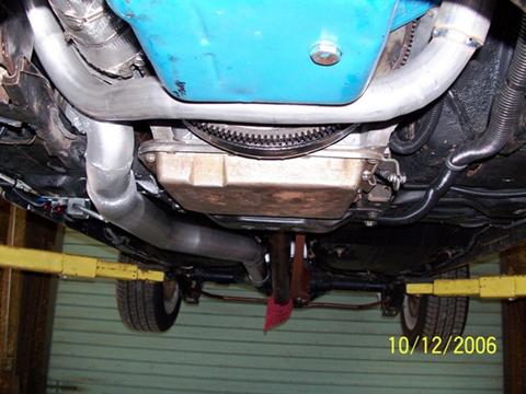
3-inch Exhaust and Flowmaster 40 Muffler
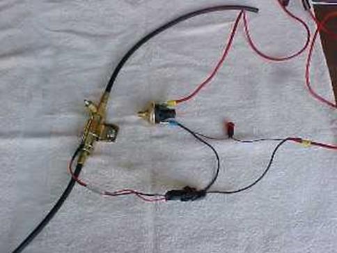
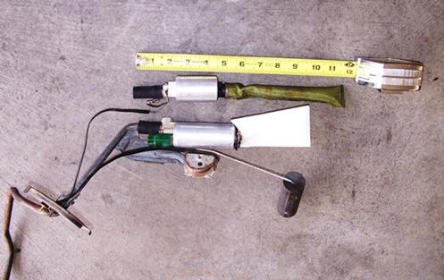
As I learned in my first project, fuel delivery is one of the major costs and headaches of doing a conversion to fuel injection. I wanted to use a stock Vega fuel tank and sender, so I was able to extend the existing pump bracket to take a Walbro 340 255 LPH pump. I had to make some wiring modifications to allow the pump to work with the Vega wiring to the top plate, but got solid contacts and grounds. You will also need to add some type of fuel pulse damper to prevent the pulsation caused by the injectors cycling from causing excessive banging and possibly damaging your fuel system. I found the same kind of corrugated tubing GM uses in the canister-type fuel modules in late-model EFI vehicles at Auto Performance Engineering (http://www.autoperformanceengineering.com/ ) . The secret is not to cut the tube, but leave it long and create a loop in it between the tank pick-up line and the pump output nipple to act as a “bungee cord” in the fuel system and reduce pulsation shock.
Fuel Pulse Isolation Tube
Since I didn’t add a baffle to the tank, I needed to ensure a constant fuel supply under lateral acceleration. I found that Walbro made a multiple pick-up system (also sold by Holley) that used check valves to prevent cavitation. I threaded a brass hose nipple fitting into the plastic end of the pump pick-up below the screen and connected three pick-ups in series into the fitting with 3/8 inch fuel hose. If you need to put a piece of high pressure hose in your fuel tank, be sure it's rated for in-tank use [SAE J30R10]. Your typical parts store high pressure EFI hose is only rated for outside the tank used [SAE J30R9]. That hose will turn to mush in no time.
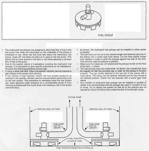
Fuel Tank Pick Up
As much as I thought that this alternative to a baffled tank
or a sump would provide reliable fuel delivery, this proved not to be the case.
Anytime I get below ½ tank, I would hear the pump working and experience
cavitation resulting in heavy detonation when either accelerating or cornering
hard. This could lead to a blown head gasket, burned pistons, and other
severe engine damage. I contacted Mark Rock, one of the premier Cosworth
collectors and mechanics, about using a baffled Cosworth Vega tank with my
existing modified Vega pickup/sender assembly. Mark agreed to do a
complete rebuild of a Cosworth tank to provide constant fuel to the pump
pickup. I purchased a new Walbro pump from Auto Performance Engineering
and modified the lower fuel pump hanger bracket to accommodate the extra length
of the pump. The pick-up sock that sits in the tank baffle is actually
the replacement Vega/Monza part I found on the rack at my local
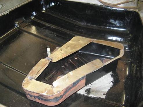
Restored Cosworth tank with baffle
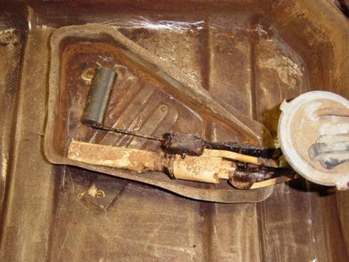
Tank Baffle and Vega Pump/Pick-up
Longer Walbro pump vs. Stock Vega Pump
I had a local radiator shop add a 5/16 inch return pipe to
the top plate, and braze 6AN male fittings on the ends of the existing supply
pipe and new return. Sherman and I then went to a hydraulic supply shop
in
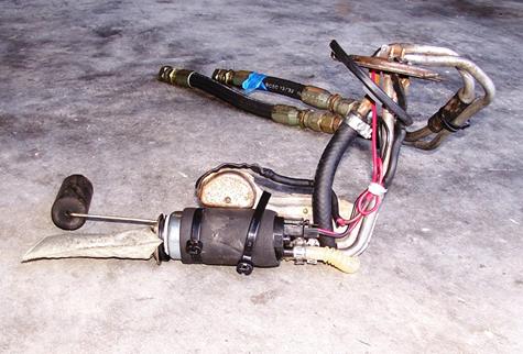
Fuel Pump Assembly
Supply and Return Hard Fuel Lines
Custom Return Flex Line and Fitting
One of the popular upgrades to the Turbo Regal is a “Fuel Pump Hotwire Kit”. It uses the existing 16-gauge fuel pump power wire to actuate a relay connected to a 10-gauge wire straight from the battery to the fuel pump power connector. These are available from many companies, but the least expensive is from Full Throttle Speed: ( http://www.fullthrottlespeed.com/ ) . Because of the age of the wiring in the Vega, I decided this was something I had to have. You can read more about the installation by clicking here: http://www.installationinstructions.com/102028.pdf .
Lubrication and Cooling
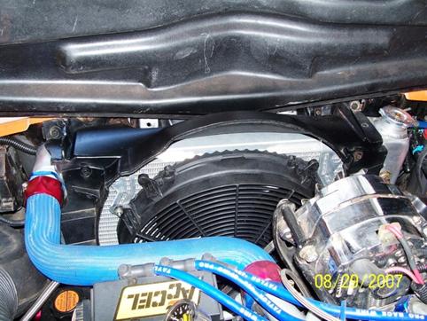
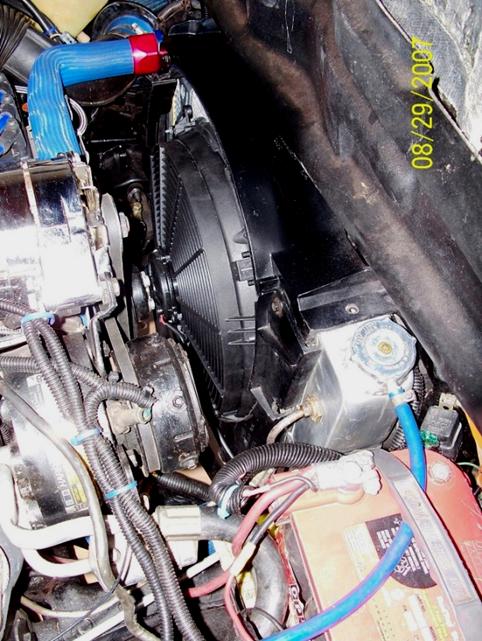
I started by using a re-cored 3-row
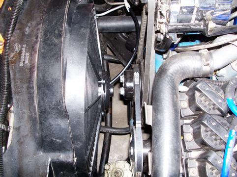
Zirgo Fan in
Since the turbo is not intercooled, maintaining a good supply of cooled oil to the bearings is critical. Oil is supplied to the turbo from the port on the block where the oil pressure switch fits on a non- turbo engine. The oil pressure switch is retained by using a brass t-fitting. I am using a Kenne Bell High Volume Oil Pump kit with an aluminum spacer, longer gears, and a steel thrust plate. The oil flows through a sandwich-type Grand National oil cooler adapter and through an oil cooler in front of the A/C condenser. After dealing with leaking stock Grand National oil cooler lines, I used the same 200 PSI hydraulic hose and fittings that were used for the fuel flex lines to make my own oil lines from the sandwich fuel filter adapter to the cooler. They leaked just as much as the stock lines, so I replaced them with pre-made 48” Trans-Dapt oil cooler lines. They cut down on the leaks, but there are still a few drips from the oil cooler and the filter adapter that I have not been able to eliminate. Fortunately, they are small enough to live with.
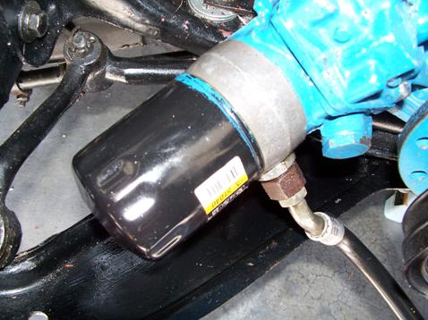
Oil Filter/Cooler
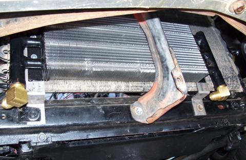
Oil Cooler
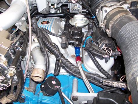
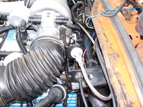
Vacuum
Since a couple of the vacuum ports were damaged, I replaced
the plastic vacuum block on top of the throttle body with a billet aluminum
piece from John’s Performance. Because the ’84-87 Turbo
Regals used an electric Powermaster brake booster, the normally-unused large
port on the vacuum block must be used to supply vacuum to the Vega power brake
booster. I installed a mechanical vacuum/boost gauge that takes its
signal from the back of the intake manifold plenum after the air is turbocharged.
(NOTE: The transmission vacuum modulator must not see boost pressure. DO NOT
HOOK THE TRANSMISSION VACUUM LINE HERE!) I also incorporated a blue boost
light off a
Accessory Mounting
The stock ’84-’85 Buick A/C and Alternator
accessory mount would not work with the cast exhaust manifolds. After
looking at several different ideas, I concluded that the best mounting system
was the stock ’79
Modified Buick ALT brace with H-body Accessory Mount
Power steering presented a bigger challenge. The stock H-body power steering pump, reservoir and mount would not allow me to use the Buick ignition and coil pack mount. The Buick P/S system was tilted toward the LH side of the car, but it hit on the power steering box. I wanted to keep my power steering, so I had to find an alternate system. I found a CV Products NASCAR-style Buick P/S mount for use with a Type 2 Saginaw pump. It needed to have the mounting legs shortened to line up with the V-6 pulley, and two of the bolts needed to be counter-sunk to allow me to mount a pump with a built-in reservoir. I searched several parts websites to find the right pump and reservoir combination, and found that the power steering pump off a 2000 Cadillac with the Northstar engine would work perfectly. The pressure line fitting needed a brass adapter from the H-body flare fitting to an o-ring fitting on the pump. A Borgeson billet V-belt pulley was pressed onto the pump, and everything lined up perfectly.
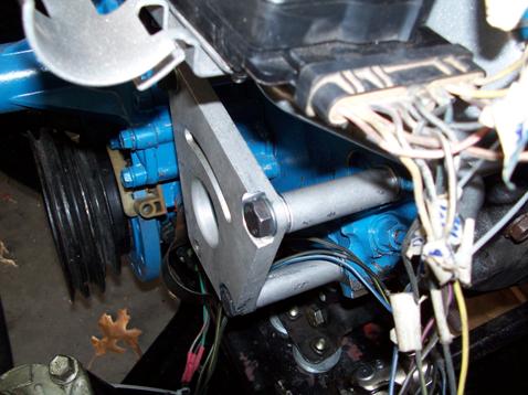
Modified CV Products NASCAR P/S Pump Mount
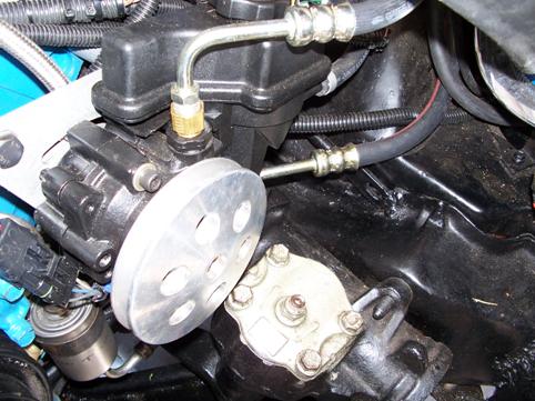
Cadillac Northstar Saginaw Pump and Reservoir
Steering and Suspension
A standard H-body

Flaming River Steering Coupler
Drivetrain
The transmission I selected is a Buick/Olds/Pontiac TH350C with a 2800-stall lock-up converter. It was rebuilt by Ronnie Smith Transmissions and features Kevlar clutch packs and a hardened input shaft. The advantage of the TH350C is that it is cheaper and stronger than a stock 2004R, it fits in the Vega chassis without modification unlike the 700R4, and allows the use of the stock torque arm. The Buick ECM takes a signal from an internal 3rd gear pressure switch and sends it to the 3rd and 4th gear input pins of the computer to make timing and spark adjustments. The computer then sends a signal back to control the 12-inch heavy-duty lock-up converter with anti-balloon plates and heavy-duty clutches from Pat’s Performance Converters. A dual connector brake switch provides positive cut-out of the lock-up function when the brakes are applied. I also added a normally-closed guarded switch to the dash that allows me to manually cut out the lock-up feature
Since the Buick ECM uses a two-pulse vehicle speed sensor input, I put a JTR Conversions 12PRS two-pulse VSS drive between the speedometer cable and the speed drive on the transmission. This is highly recommended for a street-driven car, because it prevents stalling when the car is coasting to a stop and at idle.
I was unable to find a TH350 kick-down cable that was ling enough to run from the transmission to the throttle bracket on the sideways-mounted throttle body. I had to order a custom cut-to-fit cable from Lokar that was 12” longer than their longest standard TH-350 cable. Note that the 2004R and 700R4 cables are long enough, but neither will work with the TH350C.
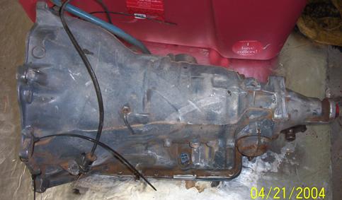
TH350C BOP
Lokar Kick-Down Cable on Throttle Bracket
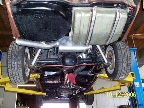
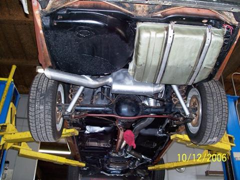
7.5-inch Rear End and V-6
Axles and Brakes
The front spindles, rotors, and calipers were swapped for a set of low-mileage 2002 S-10 pieces (with provisions for ABS). The upper conrol arms were modified to accept S-10 ball joints, and Bob Gumm’s adapters are used to allow the S-10 spindles to work with H-body lower ball joints.
The rear axle is upgraded from a stock open rear to a
7.5” 28-spline Torsen Limited Slip rear differential with
Rear brake drums are new replacement S-10 pieces, and the rear brake cylinders were upgraded to new replacement S-10 ¾-inch bore cylinders. The master cylinder is from a Jeep CJ7 and mounts perfectly to the stock Vega power booster. I retained the stock Vega proportioning valve and the brake lines fit the Jeep master cylinder without any modification. If you want to read more about how to convert to a five-lug front and rear suspension, go to www.v8monza.com .
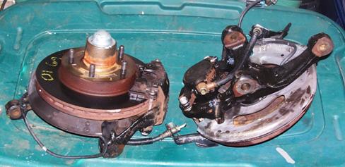
Late-model S-10 front spindles and brake
Jeep CJ Master Cylinder
Adding Hydroboost
After several months of driving, it became obvious that my engine vacuum was marginal for powering the vacuum-boosted power brakes. I rarely saw more that 15” at idle, which is less than desirable for most power brake systems. Since I didn’t have room for a vacuum pump or holding tank, I decided the best solution would be to replace the vacuum booster with a Hydroboost unit. Several complete kits are available through aftermarket vendors, typically selling for $600 or more. Since they all have the Bendix Hydroboost unit as the core piece, I decided to look at my local wrecking yard for one from a late-model GM truck. I found one from a 2000 Chevy ¾-ton truck for $50.00. Using the part numbers from the Hydratech Braking website (www.hydroboost.com) I ordered a set of Aeroquip Teflon hoses, AN6 fittings, and adapters to connect the hydraulic brake booster between my power steering pump and steering box. I had to modify the mounting plate by flipping it front-to-back, inverting it, and drilling new holes for the studs from the brake pedal that come through the firewall. I also enlarged the hole where the rod went through the firewall to the pedal. By mounting the Hydroboost unit with the accumulator on the lower right side and the hose connections on top, I cleared the steering shaft rag joint by about ¼ inch. I cut off the end of the actuator rod, threaded it with a 3/8- 24 die, and screwed on an adjustable clevis pin bracket that attaches to the brake pedal assembly. High pressure steering fluid flows from the Saginaw Type 2 power steering pump outlet to the Hydroboost input, then from the Hydroboost output to the power steering box high-pressure input. A low-pressure rubber return hose connects to the power steering box return line with a brass t-fitting. A small in-line filter keeps contamination out of the reservoir fluid. I did not even disconnect the master cylinder when I installed the Hydroboost; I simply unbolted the MC and proportioning valve from the vacuum booster and left inside fender and moved them forward, then pulled them back into position and bolted them back into place. This system provides a major improvement in pedal feel and pressure. Now I no longer have to watch the vacuum gauge and pray when I come to a stop light! The original junkyard Hydroboost started leaking in summer, 2007 and was replaced with a rebuilt unit—so far, no leaks!
Hydroboost Installed
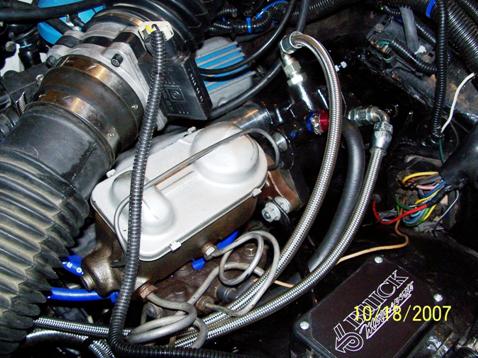
Instrumentation and controls
The stock Vega GT dash is retained with some added features. As mentioned, a two pulse JTR Vehicle Speed Sensor is used at the transmission speedometer pickup to send a speed signal to the ECM. The speedometer cable then attaches to the VSS. Tim McCabe reprogrammed the tach for a V-6. The tach signal comes from the white tach wire on the ECM. The coolant temperature gauge is stock Vega with the standard sender installed in the upper intake manifold. I also retained the Vega GT volt and fuel gauges. I added an Autometer mini oil pressure gauge in the clock location with the pressure sender pick-up coming of the right galley plug in the back of the block. This required some ingenuity and tube bending. Fortunately, Sherman Wright knew exactly what kind of fittings were needed, and figured out how to route the lines so the sender would be at the top rear of the block We used a ¼” brass pipe fitting into the block with 90-degree elbow and a brake flare fitting on the other end. This goes to a 5/16” steel brake line, then out through a hole in the block flange to an adapter that the sender threads into. Use RTV or Teflon paste on all fittings if you install the sender lines this way. We found after initial start-up that the red RTV on the elbow fitting into the block eliminated any leaks from that connection, but there is a very small drip from where the brake line threads into the elbow fitting. Unfortunately, I would have to drop the transmission or pull the engine to fix it. Fortunately, it is small enough to live with.
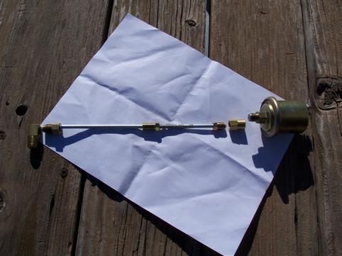
Oil Sender Parts
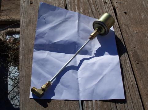
Oil Sender Assembly
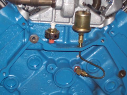
Oil Sender Installed
All “idiot light” functions including the
“Add Coolant” light are retained. An amber Check Engine light
is mounted in the clock stem hole. I epoxied a dual gauge pod onto the
left A-pillar cover to house a vacuum/boost gauge, boost light, and
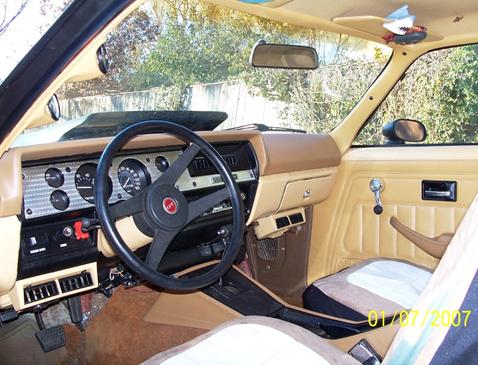
'77 Vega Dash and Console Mods
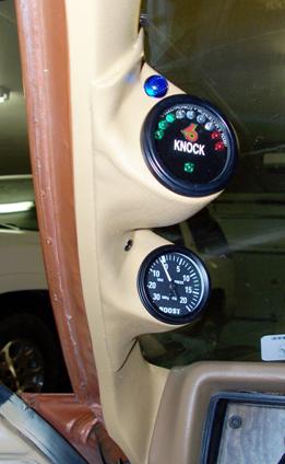
Vac/Boost and Knock Gauge Pod Detail
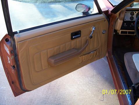
Door Panel
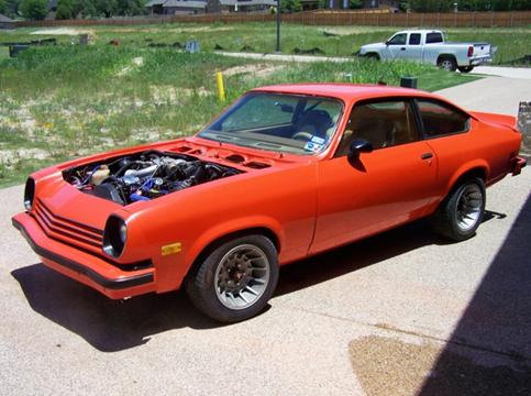
Wheels and Tires
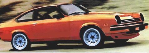
In “Building the V-6 Vega” by John Thawley, there are several pictures of a Vega with 13” American Racing “Vector” wheels. These were used on a variety of cars in the ‘70’s and ‘80’s; most notably the Dodge Charger and the Buick Grand National and Turbo T-type. Because they looked so good on the cars in Mr. Thawley’s book, and they fit the Turbo Buick theme of the project, I decided I had to have a set on my car. They have been out of production for quite some time, and are getting expensive and hard to find. Fortunately, the “Dukes of Hazzard” movie has brought them out of the woodwork; and by doing a search for “General Lee Wheels” on eBay, I turned up a set of Appliance Turbo wheels with the correct GM 5 x 4.75” lug pattern. The front wheels are 14” x 7” rims, and the rears are 15” x 7”. I modified a set of plastic center caps I found on eBay designed for Porsche 914 wheels to fit the center hole by heating the mounting tabs with a heat gun and gently bending them. Black RTV helps hold them in place. They are trimmed out with 1 7/8”- diameter Buick “Turbo 6” logos.
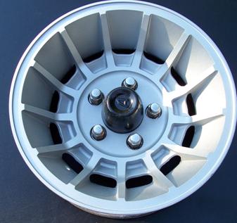
Appliance Turbo Wheel
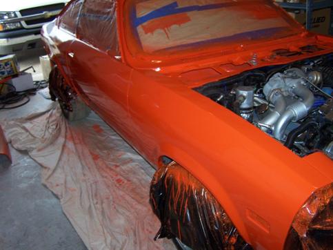
Body
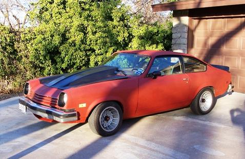
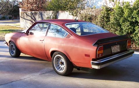
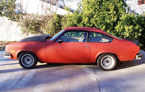
I painted the car with red primer until I could afford a good-quality paint and body job. The hood is a Glasstek cowl-induction bolt-on with a 4” rise to provide clearance for the turbocharger. I insulated the underside of the cowl cavity with Thermo-Tec heat and sound insulation material. A front air-dam/spoiler will replace the stock Vega air deflector under the front lower valence. A rear deck lid spoiler is mounted on the hatch. The radio antenna is an electronic mast antenna mounted on the rear of the roof line as seen on modern sport/touring coupes. The 1977 black window bezel treatment is used instead of the polished aluminum from earlier Vegas. The rear taillight panel is blacked out like many of the Chevy SS models of the mid ‘70’s. Bumpers will be painted body color, with the stock black rubber strips.
Turbo Vega Body Concept

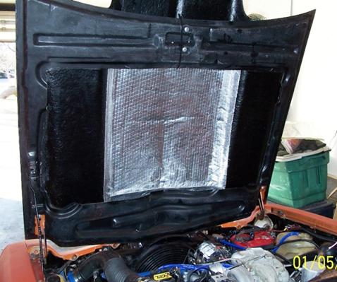
Thermo Tec Hood Insulation

Final Set-up!
Initial Start Up—Lights and Codes
After pumping up the oil pressure to 40 PSI and re-setting
the base timing on the cam position sensor, it was time to try to start.
Repeated cranking yielded nothing. I made
several attempts, but got no start. I tried using two different ECM's, but no
trouble codes displayed. I probed the ALDL for trouble codes and got Code
12-12-12 --that verifies a good Electronic Control Module-- and nothing more.
Then I checked for spark at the coils-- got it! Next, check for
fuel at the rail-- it’s squirting out the Schrader Valve-- got fuel! Why
won't it start? What else-- how about air? OK, I cracked the
throttle with the gas pedal-- BANG! BANG BANG! A rich dark exhaust mixture
filled the garage! Maybe a bit more-- Bang, chuga, chuga! This is starting to
get interesting (and I'm getting asphyxiated from the pig-rich exhaust fumes)
Finally, I got it to catch for a few seconds, and it starting to sound like it
might actually run, then it died! At least I got to hear it run, and a little
turbo spool.
So I'm thinking maybe I just need to adjust the Throttle Position Sensor (TPS)
or Idle Air Control motor. But now, I'm also thinking I might probe the ALDL
again and see if there are any new codes.
Here's what I pulled down-- Code 21-- TPS Circuit High. Code 22-- TPS Circuit
Low. Maybe that's because I was moving the throttle when cranking to see if it
would start? And Code 42-- C3I Electronic Spark Timing Failure. So maybe
I was right about the ignition module being bad!? Could I have screwed up
installing the TPS-- (remember it's the '86-'87 TPS on the '85, so it's
different)? Maybe my base timing is off?
I found and fixed the major problem preventing the car from running-- Since TPS
codes 21 and 22 came up, so I though maybe I should start there because I could
diagnose those with a digital multimeter. When I probed the Throttle
Position Sensor, I discovered that it was showing 4.60 volts at closed, and
0.50 at WOT-- exactly opposite to what it should be. As I mentioned,
there's a known problem with using the '86-'87 TPS with an '84-'85 throttle
body, because it works just the opposite mechanically from the '84-'85 TPS. So,
I wondered what would happen if I switched the grey and black wires on the
connector. I made the swap, and TADA! Now I got low volts with the
throttle blade closed and high volts at Wide Open Throttle, just like I
should!!! Next I re-adjusted the TPS for 0.44 volts at idle, 4.6 volts at
WOT, and tried to start. After cranking and getting nothing again, I
noticed that the LED light on the cam sensor cap was not on-- usually that
means I'm not getting power into the ignition module. So I wiggled the
connector a bit, the cam cap lit up, and I tried again--VROOM-- instant start!
It was still running a bit rough off idle, and was getting a few codes,
but basically it was the TPS that kept it from starting.
So now I had it running, but not very smoothly. I was still pulling codes-- Code 34, Mass Air Flow Low, and Code 42, C3I (Ignition Module) fault. And the car was smoking a lot! I decided to replace my Gen 2 module and coil pack with a new AC/Delco Gen 1 module and Accel DIS coil pack to see if my Code 42 would clear, but was still there after the swap. The Mass Air Flow Translator Plus ties into both the MAF and the Electronic Spark Control wiring, so maybe this isn’t two separate problems, but one problem throwing two codes. So I disconnected the MAFT+ plug to the ignition module and plugged the stock EST wires back together. That eliminated the Code 42 for the Ignition Module fault. Next, I decided to check the MAF sensor. I swapped the LS1 MAF on the Buick engine with the MAF in my 2002 Z-28. The Camaro ran fine with no codes on the MAF from the Vega, and the ECM still showed a Code 34 with the Camaro MAF. I also tried swapping an ’85 Buick MAF and running without the MAFT+, but still pulled a Code 34. Before giving up on the MAFT+, I started wondering whether it could be a wiring problem. Using a chart with output voltages for each ECM wire, a wiring diagram, and a digital voltmeter I back-probed the MAF wiring. I discovered the ground wire carrying positive voltage, and the control wire showing no volts. So, I switched them in the connector and re-probed them—BINGO—correct volts on both! I fired the car up and got NO SES light. I pulled codes again, and got solid 12’s, indicating a good ECM with no faults.
The car sat for two weeks while I was on a trip. The first thing I wanted to do when I got home was re-connect the ignition module, bolt the module/coilpack/bracket assembly to the engine, and tighten up the accessories. When I finished, I had no power to the cam position sensor and no start. By luck, when I swapped modules again, I grounded the ignition module to the engine by touching the base of the module on the power steering pulley. It was then that I discovered the module housing must be grounded, and after scraping the powdercoating off the pack bracket, I finally got everything working, running, and no codes. This explained why I was having problems with the ignition module intermittently not seeing the cam position sensor input. Lesson learned- when having multiple electronic problems, always suspect a bad ground first!
After swapping the front coils to V-6 A/C springs with one coil removed, I started a week of daily driving. The throttle response is impressive— turbo lag is minimal. I think the head work and cam selection on the basic engine work well with the turbo—as the basic engine starts falling off, the turbo kicks in and really pulls as the car revs through the gears into third.
Later that week, I started getting
a “Check Engine” light and a Code 41—Cam Sensor Circuit
Error. After running the GM diagnostic, I determined that the problem was
either in the ignition module or the cam sensor cap itself. The ignition
module was easier to get to, so I swapped modules first but I still had the
Code 41. Next, I swapped from the
The engine maintained around 190
degrees in city driving, and oil pressure is around 21 p.s.i. at warm idle
without the hood. Once I installed the cowl hood, temperatures went up
considerably, especially at highway speeds where I saw over 250 degrees when
moving the car to its new home in
Knock, Knock!
I installed a
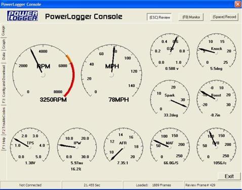
Power Logger Gauge Display
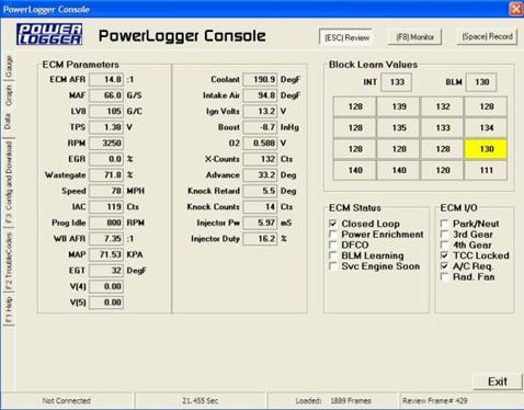
Power Logger Data Display
I can also tune the ignition advance using the MAF Translator Plus and try running some spark retard. Every Turbo Buick owner will tell you that tuning is critical, and between a good diagnostic scan tool, an Edelbrock Fuel/Air Ratio gauge, the MAF Translator Plus, and a tuneable chip, it’s only a matter of time until I optimize the fuel and spark curves to match the available boost. After returning the chip for a re-burn, I was able to pull enough timing and add fuel to run 11 PSI of boost at wide open throttle without detonation. But oddly enough, I still have detonation at light part throttle climbing up a grade at 75-80 MPH, over 3000 RPM, and 10”-0” hg of vacuum (no boost). I will need Turbo Tweak to address this area since I can’t tune there.
But at this point, the project is
a success. The car starts quickly, idles smoothly, displays no
“false knock” from valvetrain, engine, or drivetrain vibration, and
accelerates quickly under boost. After all, my goal is to eventually take
a Vega on the Hot Rod Power Tour in honor of Larry Heagren’s contribution
to the project. Running in the Hybrid class at the GS Nationals at Beech
Bend Raceway in
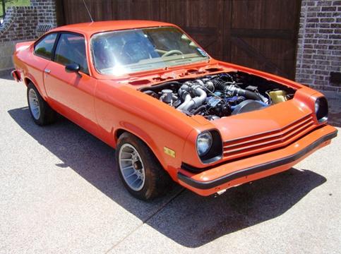
UPDATE 2008
After several years in rattle-can primer, I decided it was time to tackle paint and body on the Turbo Vega. I figured it would cost at least $5000 to have it done professionally by a body shop. When I told my wife, she said “Gee, I guess you’ll be learning to do it yourself!” Well, I figured why not? I’ve done everything else on the car myself or with a little help from my friends. I used to be a pretty good plastic airplane modeler, so I figured some of the filling, sanding, and painting skills should transfer.
After doing some research, I thought the Vega would be a good candidate for a roller paint job. Having read the original writeup by a Canadian Dodge Charger owner on moparts.com, http://board.moparts.org/ubbthreads/showflat.ph...;fpart=1&vc=1 ; plus the article in Hot Rod magazine, http://www.hotrod.com/techarticles/body/hrdp_07...nt_job/index.html ; I thought I could achieve better results with this process than doing a trial-and-error spray job at home. I wanted an orange color, but I knew I would have some areas that would require spraying, so I wanted a Rustoleum product that I could purchase in by the gallon as well as in spray cans. Surprisingly, I couldn’t find many selections in orange that would look good on my car. But I found a specialty product that was the same as their regular rust paint in the outdoor equipment line—Allis Chalmers Orange. Yep—tractor paint! It’s a dead-ringer for Hugger Orange. You can read about the process in detail at: Roller Painting Vega.
Here’s a quick summary of my lessons learned:
1. Spend as much time smoothing out all the dings in the car as you can. Even though I thought I had eliminated most of them before and after spraying with epoxy primer, I found a lot of areas I wish I had spent more time with after the glossy paint was applied.
2. Spraying epoxy primer was totally unnecessary. If I had it to do over again, I would grind down the old paint with a dual action air sander using 320 grit until smooth. Then I would fill as necessary with body filler, sand, and top with glazing putty. Any remaining low areas or rough patches can then be coated with a high-build primer from a spray can.
3. Mixture is critical to success. I recommend using a graduated mixing cup, filling to the 4 oz. line with mineral spirits, then adding paint through a strainer up to about 14 oz (+/- 2 oz depending on temperature). In warmer weather (above 80 degrees F) the mineral spirits will evaporate faster and the paint will “flash” and become unworkable sooner. To compensate for this, use a higher ratio of paint to mineral spirits.
4. Start rolling with enough pressure to get complete paint coverage on the panel, the go back over with decreasing pressure until you get an even coat with no lines, no runs, and no bubbles.
5. My work plan was to wet-sand in the morning, wipe the car down with mineral spirits, and then roll on a coat of paint. This took approximately 2 ½ hours if everything went well. Then I would let the paint dry overnight and roll on a fresh coat the following morning. I would let that dry overnight, and then repeat the process. You can apply a fresh coat immediately after wet-sanding and then wiping the surface down with a tack rag dampened with mineral spirits, but let each coat dry at least eight hours before applying another coat or attempting to wet-sand.
6. This process is very forgiving. If you screw up, just wet-sand the panel and roll on another coat. It’s also addicting, because each coat looks better than the last. Knowing when to stop is as important as knowing when to roll on additional coats.
7. Do not allow any drips of paint to dry on a finished panel! It’s very difficult to sand it off and blend it without repainting the whole panel. Immediately wipe any fresh drips off with a rag dampened with mineral spirits. The finished paint will not come off with mineral spirits after it is dry. Mineral spirits will leave the surface dull, so you will need to buff and polish to restore the shine. If you need to strip a panel after it is dried, use straight lacquer thinner and the paint will come right off.
8. You can blend in any burned-though areas with the standard mixture of paint and a foam brush followed by carefully feathering with 1000-2000 grit sandpaper and then polishing with white compound.
The process is time-consuming and labor-intensive, but it’s easy and cheap if you aren’t experienced with spraying. I liked the fact that I had fewer variables to deal with, hence less chance to screw up, and even if I did it was easy to recover. I liked the results and would do it again on a car where I didn’t care about a show-quality finish.
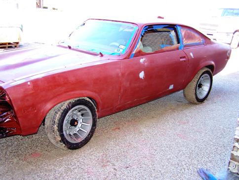
Primered and Sanded
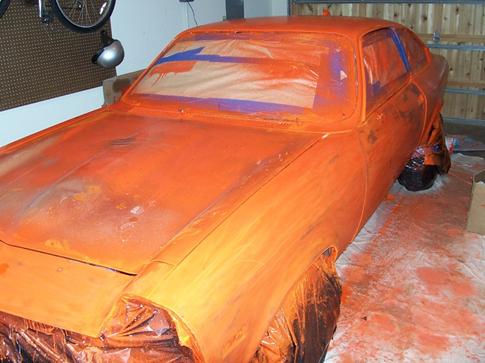
First Two Coats Wet Sanded
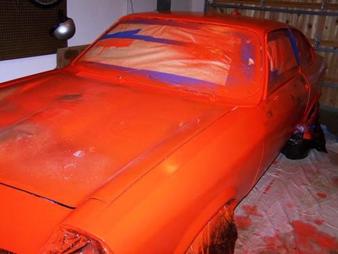
Fourth Coat Coverage
Final Eighth Coat
Polished and Buffed 1
Polished and Buffed 2
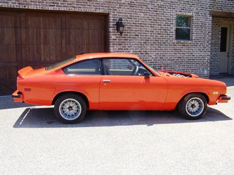
Polished and Buffed 3
Polished and Buffed 4
Alignment
After finishing paint and body work, I decided to re-address
the front end alignment. After Weatherford Front End and Brake checked it
out, they delivered the bad news—the car needed a new left tie rod, and a
new centerlink, and they couldn’t even get close on adjusting the camber.
I replaced the tie rod myself and ordered a pair of fully-adjustable upper
control arms through Chuck (cosveg76) on the h-body board. These were
$275 shipped to my door and it was money well spent. Finding the correct
centerlink was a bigger problem since Moog stopped producing them in
2003. The only source for H-body power steering centerlinks I could find
is Rare Parts in

Adjustable Upper Control Arm
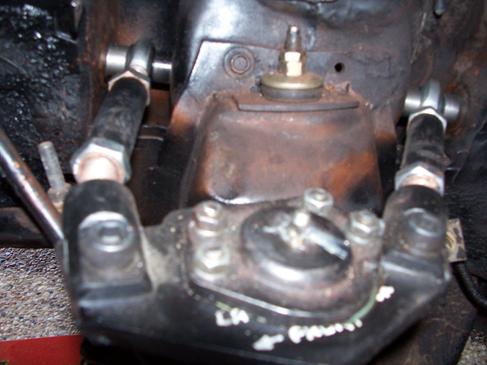
Adjustable Upper Control Arm Close-up
Race Day Results
I finally got the Vega back together for the
But I'm definitely hooked. I achieved my major goals-
finished the car, drove it to
Mike S. at
Racing Mike S. at
STRIPES!!!
Rally Stripes 1
Rally Stripes 2
Rally Stripes 3
REWIRE—2008
I finally found the source of my detonation problem. The engine likes 50-53 PSI of fuel pressure to stay out of the knock range. When the car has been driven for a while, the fuel pressure drops off to around 30-35 PSI. I tested the voltage coming off the alternator when the car is cold, and found it was right around 14.06 volts. But after the car has been driven enough to get hot, it drops off to 12.95 volts. Basically, the fuel pump isn’t getting enough voltage to run at full speed, so the fuel pressure drops off. I did some research on designing a better electrical system, and decided to put all the high-demand circuits on relays from a terminal straight off the alternator, then I upgraded the alternator to a 140-amp Powermaster, and finally replaced all the 31-year old wiring with a new harness from American Autowire. Their ’70-’73 Camaro Classic Update kit had practically everything I needed to replace the original wiring and still keep all the stock circuits with very few modifications. I highly recommend this kit for anyone who wants to rewire their H-body vehicle.
What’s next? The next
performance mod will be adding an alcohol/water injection system; a sure-fire
way to increase boost and eliminate knock. I would like to replace the
old stock power steering box with a
I hope this web article helps anyone thinking about dropping a Turbo Buick engine into an H-body, or any car for that matter. This project was easier, simpler, and cheaper than putting an LT1 into my Vega wagon a few years ago. But judging by “seat of the pants” feel, I think the performance is equivalent, if not slightly better. The true test will be if I can pull a sub-13 second time slip. As with any car project, this car will continue to be upgraded and modified over time. If you want to follow its progress, check the Garage section of www.h-body.org, or the Forums for the latest updates.
Best of luck with your projects,
Dave English
“vegatex”