|
|
by
Bill Goodwin
March 2001
Converted to HTML from MS Word by Dennis Brown--if it looks funny, blame me
I did this modification in 1985 and tried to recall the details from the pictures I took.
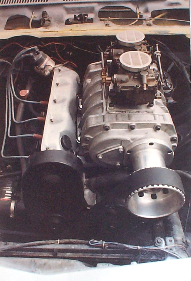
First, I did a lot of measuring and calculating for the blower positioning based on how I mounted the lower 2" wide blower pulley.(which I mounted out front of the alternator pulley)
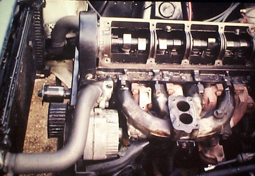
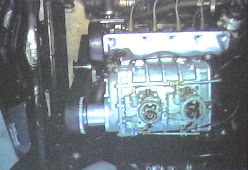
I had to determine just where the blower was to be placed front-to-rear. Once this was known, I took the cylinder head, with intake manifold bolted on, to a milling shop to have the carb mounting base and the bottom of the cyl head made parallel.(this also means it will be parallel to the crank) Although I did this with the stock 2-barrel manifold, a 4-barrel should work even better. Also, I had the two little casting nubs on the top of the head (just below the valve cover) milled to the same cut as the manifold. These nubs are for drilling, tapping and securing the aluminum blower baseplate to the head cast and not just have the intake manifold take all the stress. Additionally, to help support the weight of the blower on the manifold I fabricated a support bar which runs from the top motor mount bolt on the block up to the accelerator linkage bolthole on the side of the intake manifold.
Unfortunately, you have to use a stock 140 valve cover, modified with a hammer for blower case clearance. My cast YENKO cover had to go.

The blower manifold is just a piece of 1" thick aluminum I got from a scrap metal yard. I trimmed off the corners for looks and clearance with the master cylinder, then again went to a milling shop and had them mill down ramp areas leading to the opening in the intake manifold. (thought it would be appropriate)
These milled ramps did not exceed chamber area that the blower would cover when mounted. I had drilled the holes in the blower manifold to match up with the manifold carb-mounting studs. I replaced the studs with counter-sunk tapered machine bolts. I used allen bolts for the two additional support holes I drilled in the head casting nubs.
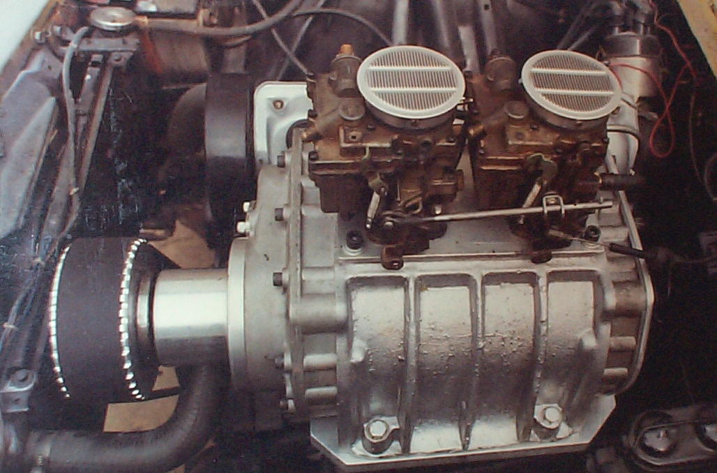
Once the head was back on and the plate mounted I did a ‘dynamic belt alignment’ by cranking the engine and moving the blower until the belt was as tight as I could get it and not wandering front or rear. I marked the aluminum base so I could drill the first hole for the blower bolts. The three subsequent holes were drilled when the belt tracking was the best. I did fabricate an idler pulley with a large washer on both sides of the pulley to help keep the belt where it should be. The idler pulley/bearing was, again, something I picked up from a scrap metal yard.
I made my own ‘2-2’s’ manifold for the top of the blower out of 3/8" aluminum plate. The accelerator cable worked fine by modifying a stock cable bracket and attaching it to the rear blower case cover bolts.
I made my own fuel line and it mated-up just fine with the existing engine compartment fuel line.
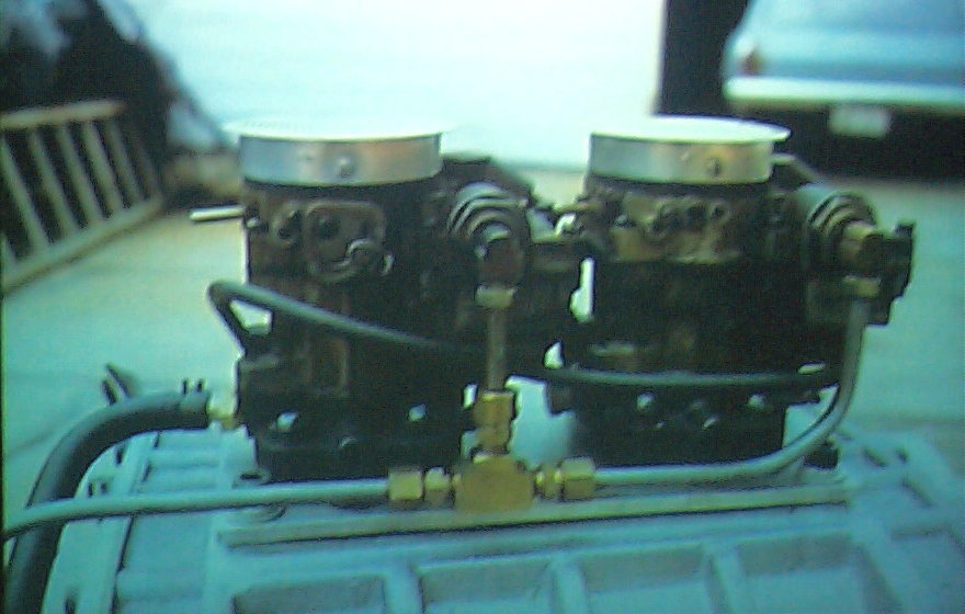
(I did have to add a supplementary fuel pump to avoid ‘starvation’.) The PCV hooked up just fine.
Feel free to contact me with any questions and have fun. I did!